











How to Install a Wire Mesh Demister Pad Step-by-Step Guide for Maximum Separation Efficiency
The installation of a wire mesh demister pads (also known as a mist eliminator) directly dictates its gas-liquid separation efficiency, operational stability, and overall service life.
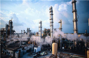
Even premium-grade demisters will fail if installed improperly. Common mistakes during installation lead to severe problems such as gas bypass (short-circuiting), droplet carryover, mesh clogging, pressure drop spikes, and structural deformation-ultimately compromising downstream equipment and reducing plant productivity.
This comprehensive guide takes you through the entire installation process, from pre-installation preparations and step-by-step mounting methods to critical safety precautions and error troubleshooting.
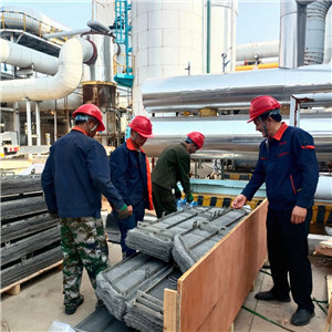
Phase 1: Pre-Installation Preparation & Inspection
Proper preparation prevents costly downtime and ensures a smooth installation sequence.
1. Verify Equipment & Process Parameters
Check the demister’s specifications against vessel engineering drawings:
Dimensions & Thickness: Confirm diameter, pad height, and grid orientation match the vessel support ring.
Material: Verify material (e.g., 304/316L Stainless Steel, Monel, Nickel, Titanium, PP, PTFE).
Structural Type: Ensure you have the correct style (single-piece vs. sectional/segmented blocks).
2. Inspect Mesh Integrity
Mesh Pad Condition: Ensure the wire mesh is flat, uncompressed, and free of physical tears or debris.
Support & Hold-Down Grids: Verify structural welds are intact, rigid, and free from warping or distortion.
Clamping: Ensure bolts, tie wire, hold-down clips, and fasteners are complete.
3. Clean Tower Internals
Thoroughly clean the internal vessel and support ring:
Remove rust, welding slag, dust, grease, and stagnant liquid residues.
Ensure the contact surfaces are smooth and obstacle-free to guarantee a tight seal.
4. Tools & Sealing Accessories
Prepare necessary tools and consumables prior to mounting:
Torque wrenches, lifting slings, and alignment tools.
Approved gaskets (metal/spiral-wound for high-temp/high-pressure; PTFE/elastomeric for ambient or corrosive service).
Chemical sealants and anti-static bonding leads where required.
Phase 2: Top-Loaded vs. Bottom-Loaded Installation
Wire mesh demisters are designed for two primary mounting configurations depending on vessel entry accessibility:
Configuration | Primary Application | Key Installation |
Top-Loaded (Top-Entry) | Vessels with removable top heads or top manways | Components are lowered into position from above; easier hoisting and positioning. |
Bottom-Loaded (Bottom-Entry) | Vessels with top height restrictions or bottom manways | Components are hoisted upward and secured from underneath the support ring. |
Phase 3: Step-by-Step Demister Pads Installation Process
Step 1: Install the Support Grid
The support grid carries the weight of the liquid-saturated mesh pad and absorbs dynamic gas impact forces.
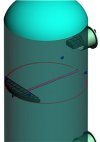
Place the support grid flat onto the vessel's internal support ring.
Ensure the grid is perfectly level without inclination.
Align the grid tight against the vessel wall without leaves or open gaps.
Securely bolt or clamp the grid to the support ring to prevent displacement during gas velocity surges.
Step 2: Position the Wire Mesh Pad
The mesh pad is the core liquid-droplet separation element and must be kept flat and uncompressed.
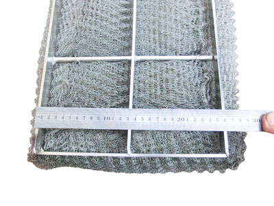
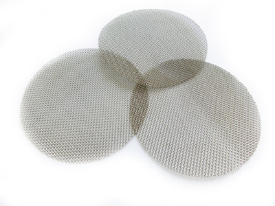
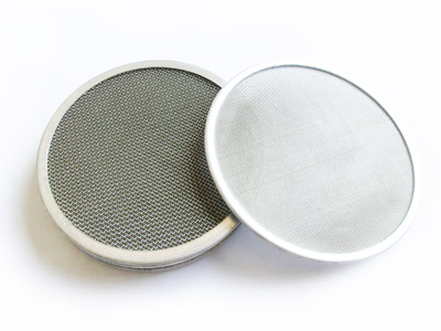
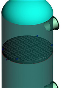
Monolithic Demisters (Single Piece): Place directly onto the support grid. Ensure the perimeter gap between the mesh pad edge and the vessel wall is uniform and strictly under 5 mm. Gaps wider than 5 mm allow gas to bypass the mesh entirely.
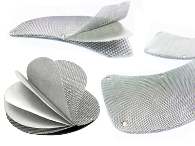
Sectional / Segmented Demisters: For large vessels, install individual blocks block-by-block through the manway. Fit adjacent blocks tightly together with zero voids, gaps, or overlaps. Secure sections using specialized locking clips or bolts to form a continuous, seamless layer.
Step 3: Mount the Hold-Down Grid & Clamping Device
Place the hold-down (top) grid directly over the wire mesh pad.
Tighten clamping bolts and J-bolts evenly across the entire surface.
Apply moderate torque: Secure the pad tightly without crushing the wire matrix. Over-compression deforms wire geometry, reduces the void fraction, increases gas resistance, and causes premature flooding.
Verify that the assembled pad cannot shift or vibrate.
Step 4: Seal Connections & Joints
Prevent gas bypass around connection boundaries:
Install process-compatible sealing gaskets along flange faces and support rings.
Use metallic/graphite gaskets for high-temperature service and rubber/PTFE for standard temperatures.
Uniformly tighten flange bolts to achieve even compression and leak-free performance.
Step 5: Pre-Commissioning Inspection & Startup
Conduct a final visual inspection inside the vessel: ensure no loose tools, wires, or debris remain.Verify all flow channels are clear and hardware is tight.Gradual Startup: Slowly introduce gas flow into the system while monitoring differential pressure, noise levels, and downstream gas purity.
Phase 4: 7 Rules for Demister Installation
To avoid severe performance degradation, strictly adhere to these seven fundamental guidelines:
Never Force-Fit Mesh Blocks: Forcing oversized sections into position distorts wire geometry, clogs local pores, and creates non-uniform gas channels.
Keep Mesh Surfaces Clean: Prohibit foot traffic or stepping on mesh pads. Protect mesh from oil, grease, paint, and welding sparks.
Maintain Strict Gap Limits: Keep perimeter clearance between mesh pad and vessel wall ≤ 5 mm to avoid gas short-circuiting.
Match Gaskets to Operating Media: Always verify thermal and chemical compatibility of gaskets and sealants to prevent melting, chemical swelling, or degradation.
Respect Gas Flow Orientation: Install demister pads strictly according to designated flow directions (e.g., bottom-to-top or horizontal). Reverse installation drastically reduces efficiency.
Use Sectional Designs for Large Vessels: For vessel diameters exceeding 3.0 meters (10 ft), always use modular sectional pads to avoid handling damage and structural sagging.
Ensure Anti-Static Grounding: In explosive or flammable gas environments, verify continuous electrical bonding between the demister grid and the vessel shell to mitigate electrostatic hazards.
Phase 5: Handling Special Demister Pads Structures
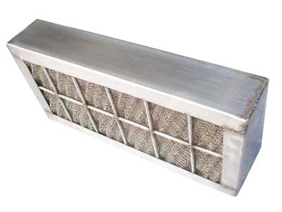
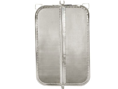
Drawer-Type Demisters: Ensure drawer slide rails are clean, level, and unobstructed. Verify locking mechanisms engage smoothly to allow quick slide-out maintenance and replacement.
Multi-Stage / Combination Demisters: Follow the strict sequential order specified in engineering diagrams (typically installing the lower coarse coalescing layer first, followed by the upper high-efficiency polishing layer). Never mix up the sequence.
Phase 6: Common Installation Errors & Troubleshooting
Errors during installation can reduce separation efficiency by 30% or more, or lead to total system breakdown. Use the table below to identify and correct common issues:
Common Error | Primary Cause | Impact on System Performance | Corrective Action |
Unlevel Support Grid | Loose mounting bolts or distorted support ring | Maldistributed gas flow, localized liquid flooding, >30% efficiency loss | Re-level support grid using precision shims (tolerance within ±1 mm) |
Over-Tightened Clamping | Excessive bolt torque on hold-down grid | Crushed wire matrix, reduced void fraction, high pressure drop | Use calibrated torque wrenches; limit compression to 3-5% of total pad height |
Perimeter Gap>5 mm | Improper sizing or shifted sectional blocks | Heavy gas bypass, severe liquid droplet carryover downstream | Add perimeter sealing strips or re-align sectional blocks tightly |
Improper Gasket Selection | Mismatch with process temp/chemistry | Seal degradation, gas/liquid leaks, potential safety hazard | Upgrade to chemical/heat-resistant PTFE, Graphite, or Alloy metal gaskets |